星期六, 9月 30, 2006

Windows CE Build Environment ToolWindows CE Build Environment Tool

寫寫這篇( http://msdn.microsoft.com/library/en-us/wcepbguide5/html/
wce50conWindowsCEBuildEnvironmentTool.asp?frame=true
)

在command window中執行wince.bat時,這個batch檔會使用三個環境變數來決定build process:

%_TGTCPU% : target cpu ?
%_TGTPROJ% :
%_TGTPLAT%
所以在執行wince.bat前,要把這三個環境變數設好。

wince.bat同時還需要%_WINCEROOT%這一個變數,告知整個WINCE source的root path。
wince.bat會呼叫一些其他的batch file來設定一個build parameter:
  • setenv.bat : ? 不知道要幹嘛
  • %_TGTPLAT%.bat : wince.bat會自動呼叫在%WINCEROOT%\Platform\%_TGTPLAT% 下的這個batchfile

無聊的..

依照他的表現,就算是不去踹這一腳,倒下去的日子也不遠了吧。
好的產品還是最重要的,不管是作口碑的高價位產品,或是C/P值高的市場殺手。對公司都有好的影響。

應該要想想,別人作不好的,自自己有甚麼能力能比他做得更好。

或許他本身就不適合作這類的產品,這也是他一直虧損的原因?

照這樣看來,就不是比誰的口袋深,能夠撐到開始賺錢,而是他註定要倒閉的命運。

最後,到了這裡....
好壞姑且不論,知名度到是有增加。

星期五, 9月 29, 2006

CE : Trace Exception Message

讀取一個invalid address,出現Data Abort。
Search "Data Abort",在 kernel\ARM\mdarm.c 中找到這個string.
在 ( http://msdn.microsoft.com/library/
default.asp?url=/library/en-us/dncenet/html/
HW_debugHardware-AssistedDebugging
WithPlatformBuilder42.asp?frame=true&hidetoc=true
) 也有提到這個file是處理所有exception的地方。
這一篇也是一篇很好說明,說明 在platformbuilder上使用hardware debugger可以做到的事和大略的debug方法。
對照message,應該是在"ExceptionDispatch( )這一個function 印出來的。

Blog不能亂寫呀...

在另一個blog隨便寫的一個為波盧加熱水的經驗, 結果有人 去看了,
是搜尋 "微波爐使用方法" 找到了.


所以說,blog不能隨便寫呀,或許是一個剛買了為波爐的新婚夫婦,面對著新微波正商著腦筋而看著我的網頁呀。

星期四, 9月 28, 2006

Writting ARM Assembly in Embedded VC - V2

上一篇轉貼別人的方法,實際照著作不OK,很奇怪,會有error說 AREA 後面的是unrecognizable opcode,所以?

MSDN上也沒有說明"AREA"這個directive,甚至連ARM Assembly source file的基本格式指令 - 設定CODE節區,Data節區... etc 也沒有。只有說...參考CE Kernel的code,所以去copy了一份flushic.s到eVC中。compile - 出現...kxarm.h 這個就是定義TEXTAREA這個MACRO的include file。

看一下,猜測 AREA這個directive大概是要
AREA |.text|,ALIGN=2,CODE,READONLY
這樣寫,把這個加在assembly source file開頭,就可以compile了,以下是測試的function:
EXPORT TestIncrease

AREA |.text|,ALIGN=2,CODE,READONLY

TestIncrease
mov r12,sp
stmfd sp!,{r4-r11,lr}
add r0,r0,#1

ldmfd sp!,{r4-r11,pc}


END
在*cpp 中使用的地方:....
extern "C" int TestIncrease(int a);
.....
int test=0;

test = TestIncrease(test);
....
可以作remote debug,在TestIncrease( )設break-point,可以看到test 這個variable由0變成1。

eVC因為不"直接支援"programmer 寫assembly source code,所以在eVC的環境和設定中都沒有相關的設定。
要加入assembly file,就要用"custom" option,自己寫入assembler command:

  1. 自己在project folder中新增一個 .s file 如: myasm.s
  2. 在eVC的Workspace panel中,source folder的部份,將myasm.s加入到source 中。
  3. 選 Project - Settings - 會出現各個configuration, 各source file的操作,選好configuration, 和myasm.s ,右邊會出現兩個tab - General, Custom Build。
  4. 選Cuntom Build,在"Commands的地方加入:
    armasm "$(InputPath)" "$(IntDir)\$(InputName).obj" 
  5. 在"Output"的地方填入:
    $(IntDir)\$(InputName).obj 
  6. OK
這樣,就可以開始編輯myasm.s了,編輯完後,用Ctrl-F7 "Compile"就可以assembly myasm.s。OK後就可以build 整個project。

Writting ARM Assembly in Embedded VC

這一篇也是轉貼,因為只有找到這一篇,所以copy下來。
是從packetmatrix forume 看到的一篇 ( http://www.pocketmatrix.com/forums/viewtopic.php?t=4063 )
內容說明在embedded VC++ 內使用assembly language。
專注在ARM。

因為embedded VC++ 的IDE要create source file,沒有assembly filed可以選,還有有關C- Assembly 間的argument passing 規則,不知道MS和ADS一不一樣。
以下就是說明。

------------------------------------------------------------------------------

1) Is there a good book about ARM assembler?
2) Can I use inline assembler in my c code with Embedded Visual C++?
3) Can I see what assembler code the c compiler creates?
4) How do I add an assembley source file to my project, and get EVC to assemble it?
5) How do I write a function in assembler and call it from the c code?
6) How are values passed to and from the assembler function?
7) Can I use any of the 16 registers for anything?
8) Useful resources.


--------------------------------------------------------------------------------

1) Is there a good book about ARM assembler.

ARM System-on-chip architecture (second edition)
Steve Furber
Addison-Wesley

As well as some chapters aimed more at hardware designers, it has an explanation of the ARM instruction set plus a complete reference of the assembler format for each one. It doesnt teach programming in any way, but if you are experienced in c programming and just need full details of the instruction set and info on how the processor works it is great.

2) Can I use inline assembler in my c code with Embedded Visual C++?

There is no supported way of doing this. You need to put your assembler in seperate functions which can be called from your c code. See below for details of how to do this.

3) Can I see what assembler code the c compiler creates?

Yes, and this is very useful for a few reasons. You can see how optimal the code being produced is, and also learn how the compiler does things. You need to:

From the 'Project' menu choose 'Settings'. Go to the 'C/C++' tab. In the 'Category' drop-down-list choose 'Listing Files'. In the 'Listing file type' drop-down-list choose 'Assembley with Source Code'.

Now the compiler will produce .asm files in the output directory which contain the assembler code with the c source as comments.

4) How do I add an assembley source file to my project, and get EVC to assemble it?

Create a blank file 'myfile.asm' in your project directory with notepad. From the menu in EVC select 'Project->Add to Project->Files' set the 'Files of type' field to 'All Files' and select the myfile.asm file. It will appear in the file list on the left, drag it into the 'Source Files' section.

Select 'Project->Settings' from the menu. On the left of the dialog: select the 'ARM release' configuration and select the 'myfile.asm' file. On the right of the dialog: select the 'Custom Build' tab. In the 'Commands' box add the text 'armasm myfile.asm' and in the 'Outputs' box add the text 'myfile.obj'. Repeat this for the 'ARM debug' configuration.

Now you can open and edit myfile.asm from EVC and it will be assembled into your project.

5) How do I write a function in assembler and call it from the c code?

First a note about the assembler source code layout. All command lines should begin with a tab. Any lines that have text on the left are labels. You need to use labels for function names and as targets for branch instructions. Use a semicolon to mark the rest of a line as a comment. The file should finish with an END command.

Example file:

Code:
1
2
3
4
5
6
7
8
9
10
11
12
13
14
15
16
17
18
19
20
21
AREA ArmGfxLib,CODE,READONLY
EXPORT FunctionA
EXPORT FunctionB

FunctionA
MOV r12, sp
stmfd sp!, {r4-r11,lr}

; useful code to do something goes here!

ldmfd sp!, {r4-r11,pc}

FunctionB
MOV r12, sp
stmfd sp!, {r4-r11,lr}

; useful code to do something goes here!

ldmfd sp!, {r4-r11,pc}

END

21 lines; 2 keywds; 0 nums; 32 ops; 0 strs; 0 coms Syntactic Coloring v0.3 - Dan East


Explanation: the AREA command gives a name to this code section. The EXPORT command makes those labels available as functions. The stmfd/ldmfd commands save and restore the registers to the stack, so you dont corrupt values that the calling function depends on.

In your c++ code add the line:

#ifdef ARM
extern "C" void FunctionA(int a, int b);
#endif

The #ifdef is because we have written the function in ARM assembler so it isnt available in MIPS/SH3 builds.

6) How are values passed to and from the assembler function?

If you declare a function of the form:

extern "C" int armfunction(int arg1, int arg2, int arg3, int arg4, int arg5, int arg6);

The first 4 arguments will be passed in the registers r0-r3. These registers will contain the passed values at the start of your assembler function. Further arguments are passed on the stack, see the code below to read them.

The return value should be placed into register r0 at the end of your assembler function (just before you return to the caller).

This works well with int's and pointers (all pointers are 32 bits). If you try and pass a structure directly as an argument it gets more complex. I advise you to only pass/return integers and pointers to/from your assembler functions, at least to start with.

Here is an example function (declared as above) which adds its six arguments and returns the result.

Code:
1
2
3
4
5
6
7
8
9
10
11
12
13
14
15
16
armfunction
MOV r12, sp ; these two lines are
stmfd sp!, {r4-r11,lr} ; standard setup code

; r0-r3 are the first 4 arguments passed

ldr r4, [r12] ; load 5'th argument into r4
ldr r5, [r12, #4] ; load 6'th argument into r5

add r0, r0, r1 ; r0 = r0 + r1
add r0, r0, r2 ; r0 = r0 + r2
add r0, r0, r3 ; r0 = r0 + r3
add r0, r0, r4 ; r0 = r0 + r4
add r0, r0, r5 ; r0 = r0 + r5

ldmfd sp!, {r4-r11,pc} ; standard cleanup and return code

16 lines; 1 keywds; 3 nums; 52 ops; 0 strs; 0 coms Syntactic Coloring v0.3 - Dan East


7) Can I use any of the 16 registers for anything?

No. You can use r0-r12 and r14 for anything you like. r15 is the program counter, if you write a value to it then execution will jump to that location. Use the branch instruction, dont alter it directly. r13 is the stack pointer, do not alter it unless you are sure you know what you are doing. r14 (which you can use) is the link register. If you want to call another function you need to set this to the return address, I will include an example in a future version of this FAQ.

8) Useful resources.
什麼時候要用?

要用 mcr, mrc 和co-processor instruction 時好像就要用到...

星期三, 9月 27, 2006

ARM MMU :Address Translation : Level One Descriptor

在ARM User Manual 上看MMU : address translation 時一直有一個疑問,作level one translation時:


mmu 的 TTB (translation base register) 內的bit 14-31


要轉換的address的 bit 20-31

組合成一個 30 bit的address
H  --------------------------L
[TTB 31-14] [ Address 20-31] 1. 0
這個位址就是level one descriptor。
descriptor的內容決定address要怎麼轉換。

問題是...address只有 30 bit呀,後面還有兩個bit怎麼辦?
都用 0 ? 那這個descriptor table不就不連續 ?

真蠢。

descriptor的size是32 bit,所以一個descriptor需要4 bytes。
最後兩個bit當然就不能用囉。


會被混淆的原因是 descriptor的內容,
剛好bit 0, 1 用作 traslation type 的id:
00 - Fault
01 - Coarse Page
10 - Section
11 - Fine Page

星期一, 9月 25, 2006

Windows : 網路ok但是不能瀏覽網頁和telnet

這一篇'是從資安論壇copy過來的,原文是 王世達 先生所作,因為太過重要,所以轉貼再這裡。
如何修復被惡意程式破壞的Winsock?
« on: August 15, 2006, 09:49:02 AM »
________________________________________
有些惡意程式(如Trojan.Riler.F、TROJ_AGENT.CAC)或間諜軟體(如NewDotNet、WebHancer等)安裝一些附加 元件至系統的Winsock2機碼中(有時候稱為Layered Service Provider, aka, LSP),以利於監視系統的網路訊息。當你(防毒軟體或反間諜軟體)不小心移除它時,會造成網路中斷或網路不穩定。如果發生這種情形,如何檢查及修復它 呢?

如何判斷Winsock2已經被損毀了呢?

方法一:使用Windows XP SP2所提供的命令(netsh winsock show catalog)
1. 按一下[開始],然後按一下[執行],輸入cmd,然後按一下[確定]。
2. 在命令列視窗中,輸入netsh winsock show catalog。
3. 如果Winsock2機碼沒有損壞且只安裝TCP/IP的話,[通訊協定]中會有10個區段,每個區段的名稱將如下所示:
‧ MSAFD Tcpip [TCP/IP]
‧ MSAFD Tcpip [UDP/IP]
‧ RSVP UDP Service Provider
‧ RSVP TCP Service Provider
‧ MSAFD NetBIOS [\Device\NetBT_Tcpip...

方法二:使用msinfo32.exe
1. 按一下[開始],然後按一下[執行],輸msinfo32,然後按一下[確定]。
2. 展開[元件],再展開[網路],然後按一下[通訊協定]。
3. 如果Winsock2機碼沒有損壞且只安裝TCP/IP的話,[通訊協定]中會有10個區段,每個區段的名稱將如下所示:
‧ MSAFD Tcpip [TCP/IP]
‧ MSAFD Tcpip [UDP/IP]
‧ RSVP UDP Service Provider
‧ RSVP TCP Service Provider
‧ MSAFD NetBIOS [\Device\NetBT_Tcpip...

如何修復已經被損毀的Winsock2呢?

方法一:
如果你的系統已經是Windows XP SP2的話,只要在命令列視窗中,輸入下列的命令即可:netsh winsock reset
不過,如果你有安裝其他的附加元件的話(如Google Toolbar),此命令會還原至只有TCP/IP的狀況。

方法二:使用LSP-Fix程式
1. 你可以從http://cexx.org/lspfix.htm下載此程式。

方法三:刪除毀損的登錄機碼,然後重新安裝 TCP/IP 通訊協定
1. 按一下[開始],然後按一下[執行]。
2. 在[開啟]方塊中,輸入regedit,然後按一下[確定]。
3. 在[登錄編輯程式]中找出下列機碼,再用滑鼠右鍵按一下每個機碼,然後按[刪除]:
HKEY_LOCAL_MACHINE\System\CurrentControlSet\Services\Winsock
HKEY_LOCAL_MACHINE\System\CurrentControlSet\Services\Winsock2
4. 提示您是否確定要刪除時,請按一下[是]。
注意 刪除Winsock機碼之後,請重新啟動電腦,否則,下列的步驟就會無法正確執行。
5. 安裝 TCP/IP,用滑鼠右鍵按一下網路連線,再按一下[內容]。
6. 按一下[安裝],按一下[通訊協定],然後按一下[新增]。
7. 按一下 [從磁片安裝],輸入C:\Windows\inf,然後按一下[確定]。
8. 在可用通訊協定的清單中按一下[Internet Protocol (TCP/IP)],然後按一下[確定],然後重新啟動電腦。

參考:
1. KB811259: http://support.microsoft.com/default.aspx?scid=kb%3Bzh-tw%3B811259
2. LSP-Fix: http://cexx.org/lspfix.htm
可惜知道得太晚,已經重灌了。

Windows真是一個奇怪的系統呀,ping得到,網路Ok,但是網頁,telnet竟然都不通。
不知道是怎樣搞出來的。

系統能作成這樣也算是偉大了。

ARM Assembly Pseudo Codes : MAP, FIELD

ARM Assembly 中MAP和FIELD是用來產生類似 C 的"structure" 的資料區塊
  MAP  0x100
A FIELD 16
B FIELD 32
C FIELD 256
以上在位址0x100的地方宣告了一個structure,A的位置是16 byte,B 32 byte,C 256 byte。
和 C的structure一樣,reference 到A時,代表位址0x100,
B 代表位址 0x100 + 0x10
C 代表位址 0x100 + 0x10 + 20

另外比較討厭的是ARM Assembly每個pseudo code幾乎都有一個簡寫符號,MAP是 " ^ ",FIELD是 " # "。

所以上例變成:
  ^  0x100
A # 16
B # 32
C # 256
要注意"#"在instruction 中代表literal。

另外,如果不是在MAP中,要宣告一塊空間,要用 " % ",使用 %符號,該位置由locator決定。

* 其他還有很多奇怪的 pseudo code代表符號,可以參考 : http://checko.blogspot.com/2005/02/ads.html

CE : Kernel Startup Sequence and some others

在MSDN 這一篇:http://msdn.microsoft.com/library/default.asp?url=/library/en-us/dnce50/html/ce50prev.asp
有說明 CE 的startup sequence..

從bootloader開始講,範例是ARM。
要配合BSP的code來看,BSP的code中,bootloader 依照boot flash type : NOR 或是NAND。而有不同。(BSP中有一個readme,說明boot environment: FLASH Layout)

NOR : EBOOT
NAND : STEPLOADER

EBOOT 就是 etherboot,支援download image from ethernet,writing to NANDFLASH。
(這個功能是因為demo board上有一個JMP可以設boot device : FROM NOR/NAND)。

STEMPLOADER是一個小size的bootloader,配合cpu NAND boot support的功能。boot時,cpu會從NANDFLASH讀取4k的data進入internal SRAM,再由internal SRAM boot。


Wakeup 和 Reset不一樣的地方在於Wakeup 時,SDRAM的內容是Sleep時的內容,沒有消失,所以只要適當將週邊再設定好,就可以回到當初sleep的狀態繼續執行。
Reset就不一樣。

這個bootloader的starup code要作的事情很多,因為不管是wake from sleep,reset 和WDT timout都是從這裡開始執行。
所以要判斷是wakeup,reset還是WDT,wake up的話,要check saved data是不是OK。restore saved data (CACHE/MMU control)。
WDT的話,要clear DRAM data。
reset的話,要將kernel從NANDFLASH load進來(C code)。


Bootloader的部份都是以EBOOT為範例解說。 -- 這部份略過,因為NAND FLASH不使用EBOOT作bootloader。

Kernel

由 Src\Kernel\OAL\Startup.s 開始。 負責hardware 相關的初始化(dram, cache...),最後計算好OEMAddressTable 的位置,當作是argument,呼叫KernelStart。
OEMAddressTable 宣告在Src\inc\oemaddrtab_cfg.inc。

KernalStart在MS的private code folder的armtrap.s(也就是說,其內容是不能在公開場合提及的)。在msdn這一篇 ( http://msdn.microsoft.com/library/default.asp?url=/library/en-us/wcecoreos5/html/wce50conNkexeBootProcess.asp ) armtrap.s 這一個assembly 不太好看,裡面包括很多部份,大部分是要setup MMU,所以有一堆Virtual, Physical 轉換。

ARM MMU architecture (furber P.302)

ARM MMU 使用 2-level page table和一個TLB(存放最近用過的translations)。
memory mapping的size可以有以下選擇:
  • Sections - 1M byte
  • Large Pages - 64K Byte,其中每16K byte又被分為一個sub page,可以分開控制
  • Small Pages - 4K Byte,分成 1K byte subpage
  • Tiny Pages - 1K Bytes tiny page
在KernelStart (armtrap.s) 中看到設定MMU Translation Table的部份,最後的 byte是1。
所以是 Coarse page - 64k per entry。

使用Corse Page,所以Address Translation 要經過兩次轉換:由 MMU的 TTB(Translation Table Base)register 和要轉換的address查表到一個descriptor,由descriptor內的


有關MMU - ARM MMU : CP15 (P.299 furber)

C3 : Domain Control - 16 個domain的access control (2 bits/domain)
C2 : Translation Table Start Address - 在RAM中存放Translation Table的start address
C8 : 控制每個domain動作 - Flush.. etc
C1 : MMU的各項funtion (enable MMU,address alignmnt fault, data cache, Write buffer...)


CE 的system call 和Linux kernel service 類似,有implement一個call-gate,將API轉為Service_ID傳入統一的kernel 介面。

Service ID 定義在oak\inc\psyscall.h

星期日, 9月 24, 2006

CE : Filesystem architecture and FileSys.exe

這一篇是翻譯這裡(http://msdn.microsoft.com/library/default.asp?url=/library/en-us/dnembedded/html/embedded06172003.asp)的前半段...
CE 的 File 操作是由 FileSys.exe完成的,也就是說,program中有關file 的操作,file的api都是由FileSys.exe 這個 progam 完成。

詳細一點說,FileSys.exe 負責 ObjectStore和Storage Manager。

CE的檔案系統結構跟Linux比較相似,存在於 Root : "\" 下。
跟Windows 的file system 有很多driver letter 為root 反而比較不同。

CE中,File Driver 會mount在 Root "\" 下的一個folder (跟linux一樣)。

FileSys.exe 含有以下三個component:
  • ROM Filesystem
  • Storage Manager
  • Object Store
Object Store實際上是在memory heap中,Object Store內含 RAM system Registry,RAM filesytem,Property Database。

Registry 是所有CE所必須的,在CE 4.0 之前,registery 都是存在RAM 中,到了CE .NET後,registery 可以在RAM 或是以file的形式存在其他storage中。

RAM filesystem和Property Database則是optional,designer可以依需要選擇是否要加入這個支援到FileSys.exe這個module中(在platformbuilder)。

RAM File System一般就會mount在root上"\",也就是說,Root就是RAM Filesystem。
RAM File system下的file會直接出現在root"\"下。

ROM File System則會mount在"\Windows"下。也就是說,CE的"\Windows" folder是read-only。

Storage Manager是CE .NET新增加的module,負責所有Storage和Storage中使用的Filesystem。
Storage Manager主要處理四件事:
  • Filesystem Filter
  • Filesystem Driver
  • Partition Driver
  • Storage Driver
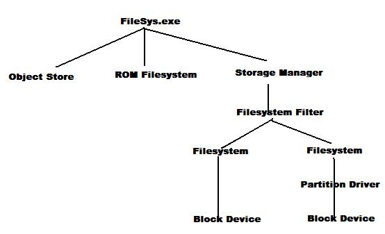
這四個driver和整個FileSys.exe的關係如下圖所示:

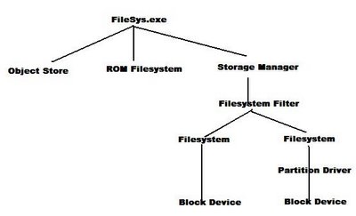
圖中可以看出,Block device負責storage hardware相關的read/write動作,Partition Driver負責在Storage中模擬出partition的動作(分割),其上是Filesystem。在Partition(在沒有partition的storage則直接對Block)做出filesystem。
上面是Filter,Filter可以讓designer implement一些像encription之類的動作
。另外,看Filter的位置,可以知道,Filter的動作只能對Block device,所以designer沒有辦法在ROM Filesystem和Object Store加上自己實做的encription動作。

除了實際的Block device外,Storage Manager也可處理network filesystem,只要filesystem implment所有 Storage manager和Filesystem Filter所需要的API,就可以完成一個實際的storage。

以下說明system loading filesystem的動作:

boot - NK.exe 啟動,將在ROM Filesystem中的FileSys.exe 載入,FileSys.exe將在ROM 中的registry 載入到RAM中初始化。
FileSys.exe讀入registry,依照registry中的設定值load其他的driver,第一個load的是device.exe,這個driver依照HKLM\Driver\building的內容依序將其他driver load進來。
Block driver也會在這個registry key下,所以也會被load進來。Block Driver "advertise" 一個特殊的class id : BLOCK_DRIVER_GUID {A4E7E......略}。

FileSys.exe中的Storage Manger提供一接口,接收所有block device driver loading, unloading時發出的通知訊息。
當有Blockdevice driver loading時,Storage Manager 對block device driver作open動作,並且查詢他的profilename。
每個block device都在registry中存有一個自己的PROFILE,說明這個block device使用的partition driver和filesystem driver種類。

Storage Manager 知道了block device使用的partition 和filesystem driver後,就去把這些driver load進來。

partition driver load進來後,Storage Manager請parition driver將block device中所有的partition 列出。同時列出partition使用的filesystem,Storage Manager再將filesystem driver loading進來,將對應的partition mount到對應的目錄。

GPL Violation : D-Link

上一個廠商好像是ASUS吧,不過經過那次之後,ASUS似乎已經和open source合作得非常好了。

這一次是D-Link。

http://gpl-violations.org/news/20060922-dlink-judgement_frankfurt.html

為了真的維護gpl,gpl-violations.org成立。
這個案子就是其中一項,大概是說D-Link的DSM-G600 這個NAS產品使用了GPLed Source Code。
但是卻沒有依照GPL規定將source code公佈(或是提供給產品購買者),gpl-violation.org通之後,D-Link好像不承認,最後gpl-violation.org利用reverse-engineering提出證據,所以D-Link只好答應停止販賣這項產品(但是source code還是不提出),依照gpl,應該是有權要求全面回收,否則就要提供
source code,但是gpl-violation.org 也答應D-Link以不再販賣終結這個案子,但是要求D-Link支付當初reverse-engineering所花的錢。

結果?

D-Link 竟然向法庭提出這是gpl-violation.org的不當要求????

今年 9/6,德國法庭判定這並非不當要求,D-Link應該要支付這筆費用。

那,,,這筆費用到底是多少錢呢?

----- 300 EUR

(我不太暸解,是全額300 EUR還是雙方議價的差距是 300 EUR ?)


真是不可思議的D-Link呀。
這麼心不甘情不願,去用CE就好了呀。
(或是用bsd,但是driver比較不全)

真是讓人看不起....

星期六, 9月 23, 2006

最後的夥伴 - 海賊王 428

魯夫終於打敗CP-9,但是已經全身無法動彈。
四周都被海軍軍艦包圍...唯一的逃脫船也被擊沉,
所有海軍艦砲,瞄準著魯夫一行人...即將發射...

還有希望嗎?

騙人布隱隱約約聽到還有一個夥伴的聲音,,,"向大海去吧!向大海去吧....",

海軍艦砲發射!

"大家跳向大海吧!我們還有一個夥伴,來接我們了!" : 騙人布大聲呼喊著。

海賊團員們向著大海一躍而下! 在海上,迎接著他們的是.....飄揚的 草帽海賊旗


黃金梅利號


星期三, 9月 20, 2006

CE: mismatched time stamp on .rel file for module ...

在作CE image build時,因為整個build (build and sysgen,又check "clean before build)需要很長的時間( about 1.5 hr @ 2.5G 512M)。
所以通常都會開啟"Open Release Directory" 的command視窗,到有修改的folder中手動
build -c
作local build,然後再用platformbuilder的"make run-time image"來make image。
或是在command下用
 makeimg
來作相同的動作。
使用platform builder的"make run-time image"的好處是log會在log視窗中,可以看到全部,用command下的話,受限command 的buffer,只有最後幾行可以看到。
這樣作,有時候會出現
"mismatched time stamp on .rel file for module XXX.."
的warnning,然後有時候會導致error。
解決的方法是用用platformbuilder的"Copy File to Release Directory"(或是在command下 buildrel )。
之後再makeimge,錯誤就會消失了。

...當初是猜測既然是file time stamp 不符,所以把所有file的time stamp改掉不就可以... 可惜我不知道windows 有沒有 "touch" 這樣的命令。所以只好將releae folder刪除,一一由build folder copy到release folder... 後來才看到有這樣的command,試試,果然OK。
:)

UDA1380 - I2S Code-Decoder

  • I2C控制介面
  • I2S 資料介面
  • AD : Audio in -> I2S 8~55kHz
  • DA : I2S ->Audio 8~100kHz
  • Sampling Resolution : 24bit Max (?)
  • In/out path的clock和Gain AMP可以分開power down。
  • AD, DA可使用不同的freq : system clock或是由I2S的Word Selection Clock 鎖相。
  • 提供一個單音輸出和一個16 ohms立體耳機輸出端

以下是DAC部份:

system clock: SYSCLK

DAC的內部clock是128 sampling frequence (1 data value need 128 clocks internally).
這個內部clock要由SYSCLK產生,所以外部IC要提供正確的SYSCLK和設定好UDA1380的register,讓內部確實產生128 fs 的clock。

一般的音源sampling freq是44.1kHz (CD是96kHz),假設master cpu產生256fs的話,SYSCLK就會是44.1k * 256 =11.2896MHz。

進入UDA1380後,要設定register00[3:2] = UDA1380才能產生128fs 的clock。

* 從UDA1380的datasheet來看,register00[3:2] 的value:
00  256fs
01 384fs
10 512fs
11 768fs
所以SYSCLK最低是256fs。

星期二, 9月 19, 2006

Make Binary Image Tool and Add file in Images

有關make binary image 的動作,可以將 make run-time image後,PB的"Build" output windows中的log copy 出來看,可以知道make binary image的整個動作(依序run哪些command),再利用PB 的help search這些command 。
ms-help://MS.WindowsCE.500/wcepbguide5/html/wce50conMakeBinaryImageTool.htm

make image時 Makeimg.exe 會呼叫以下program:
  1. NLS(Native Languege Support) Compression tool (Cenlscmp.exe) enable
  2. Fmerge.exe - merge multi bib , reg, dat, db to one.
  3. RegComp.exe (Registry Compression Tool) 將Reginit.int 轉為binary 模式(Default.fdf),這個file會被包在image中(在ce.bib中可以找到)。
  4. Res2exe.exe (Resource Update Tool) : 將DLL.EXE 中與語系,地區相關的resource file換掉。
  5. Txt2ucd.exe (Text to Unicode Tool) : 將Fmerge.exe產生的Initobj.tmp中的ASCII string轉成Unicode string,放在Initobj.dat
  6. Romimage.exe (Rom Image Builder Tool) :根據 Ce.bib 的內容,將file 安排好。產生nk.bin。
喔,很多。大部分make image的動作都在這裡說明了,應該要看一下。

下一個,將檔案加到 image中:
ms-help://MS.WindowsCE.500/wceosdev5/html/wce50tskAddingaFiletoanOperatingSystem.htm

分成兩步驟
  1. 將檔案copy到release folder中
  2. 告訴pb 將檔案加到image中
copy的動作可以用手動或是自動,手動就不用說了,自動的話可以利用PB的Platform Setting功能,在Prebuild 過程 加入copy動作。

告訴pb 的方法是 將要加入的file加到Project.bib中的FILE Section。follow bib的格式:
FILES
; Name Path Memory Type
; -------------- -------------------------------- ------ ----
<file name> $(_FLATRELEASEDIR)\<file name> NK S
Name會檔案在Image中的名字。

有關bib的file 欄位說明,在
ms-help://MS.WindowsCE.500/wceosdev5/html/wce50confilessection.htm

FILE section的內容和MODULE section一樣,但是Romimage.exe會壓縮FILE section,

Name : 該file在image 中的名字(memory table中的名字)。
Path : 在image中的path (folder ?) - 但是實際上看起來好像是source file path/name。
Memory block : 在Config.bib中MEMORY section 宣告的區域
Section override :
Type : file type,可以是:
  • S : system file,只有OS可以用
  • H : hidden,不會顯示在一般的目錄中
  • U : Uncompressed
  • N : untructed module
  • D : 不能debug

PB的output windows在make run-time image時會輸出最後的image map,內容包括最後各file, program 的各section 的location, size。
最後還會列出Starting ip (image entry)

CE Command Tools - fmerge

在PB help裡:

Makeimg.exe 呼叫這個command將:
1. 所有 *.bib 合並成一個 ce.bin
2. 所有 *.reg合併成一個 Reginit.ini

所以在上述兩類(bib, reg)檔案中可以使用以下instruction 控制fmerge.exe:
#define
#undef
#include
#error : 輸出message並且停止執行
#message : 輸出message

在這些instruction 中可以使用:
&&
||
==
!=
變數的部分(用#define 定義的),可以用$( )來代表。
雖然沒有說明fmerge.exe如何將所有bib, reg合併成 ce.bin, reginit.ini,但是也可以知道最後的 relocation definition 在 ce.bin。
registry definition 在 reginit.int

還有這兩個file都是在 PBWorkspace下Reldir\XXX_Release

星期六, 9月 16, 2006

New iPod Nano - No Chip's Mark

這一篇文章 : http://www.ddj.com/dept/embedded/193000928?cid=RSSfeed_DDJ_All

說到這次新release的iPode Nano,內部IC的標誌都已經被mark掉了,大概是為了避免上次一樣的事件,被人家算出cost,而發現Apple大賺了一筆。

但是 文章中還是猜測了一下...

代替原來PortalPlayer的是Samsung的arm chip。
還有兩顆大概是Wolfsan的codec和Philip的power control 。
據說 這次新的 Nano,雖然價格比較低,但是Apple賺得更多 (換Vendor的關係?)。

聲音呢? codec用一樣的,音質大概沒差吧。

星期五, 9月 15, 2006

WINCE Driver

Windows CE 的driver source,是用類似dll export的方式提供呼叫介面,
source code中,使用一個 ***.def 將module name和要export的function name列出,以下以MYDRIVE的MYDRIVE.DEF為例
LIBRARY         MYDRIVE

EXPORTS
MY_Init
My_DeInit
My_Open
My_Close
My_PowerDown
My_PowerUp
My_IOControl
這樣

OAK - OEM Adaption Kit

在PlatformBuild中到處出現的 OAK 是什麼意思?

在 http://acronyms.thefreedictionary.com/OEM+Adaption+Kit+for+Windows+CE+(Microsoft) 找到,原來是 " OEM Adaption Kit"。

星期二, 9月 12, 2006

eVC : Debug with emulator - first look.

eVC 內建Emulator,在寫application時,可以用這個emulator作簡單的debug (當然,跟hardwae相關的就不行)。

開啟Project時記得要加入Emulator 這個configuration。(不然就要在 Build - Configurations - Add 增加你要的Configuration)。

Build - Set Active Configuration 選 Emulator,
之後,就follow一般programming, building 步驟就可以,最後,用Build-Start Debug - Go。就會啟動emulator。

Project可以配合不同的Platform (SDK),每個Platform(SDK)又有不同的configuration。
在Build-Set Active Platform 可以選擇你要使用的Platform (STANDARD_SDK or YourPlatform_SDK)。
之後在 Build -Set Active Configuration 選你要用的configuration (Emulator Release/Debug , ARM Release/Debug)。

在 Tools - Configure Platform Manager 可以看到所有的"Device "(?)。在這裡設定對Project與device的關係。
例如有一個STANDATDSDK_420底下有一個device : STANDARDSDK_420 Emulator,選"Properties"可以看到相關設定:
  • Transport : TCP/IP Transport for WinCE
  • Startup Server : Emulator Startup Server
另一個Platform "YourPlatformSDK",Transport和Startup Server都是選 ActiveSync。

這樣很複雜的,分散在各處的,名稱不一致的,很容易搞混的,不容找到的Platform - Configuration - Device 之間的設定,決定了Project的debug動作(是經由ActiveSync 與target 作remote debug還是用emulator作debug)。

星期一, 9月 11, 2006

eVC : Compiling/Linking Directory Setting/

Tools - Options - Directories - Show drirectories 有
  • Executable files
  • Include files
  • Library files
  • Source files
可以設定Build related directories。

如果只是Project Dependent path,要在
Project - Setting - C/C++ - Preprocessor - Additional include directories

Linker - General - Object/library modules

多組path以空格分開。

Offline Blog Editor : Zoundary

Blog 離線編輯軟體 : Zoundary。是free 的,Not sure if it's GPLed .

Zoundary Blog Writer

好像沒辦法過firewall/proxy

星期五, 9月 08, 2006

SDRAM Self-Refresh

Chip 的DRAM Controller提供兩種refresh mode : Auto Refresh 和 Self Refresh。
(? 依據DRAM的說法,self-refresh功能是由DRAM自己提供,而不是DRAM Controller)。
另外,還有一項跟DRAM的特性有關的是Refresh Period。

Self-Refresh 通常用在power-saving 模式,或是sleep mode。可以少耗電。
refresh period 越短,耗電量越大,為求省點,通常都盡可能的將refresh period加長。
但是period 太長是有危險的,一旦不足以保持DRAM的內容,就會造成data lost。

所以適當設計refresh period,是一個power and performance 的trade-off。

另外一個需要考慮的因素是溫度,當溫度高時,電晶體介面電阻變小,data cell的discharge current變大,所以DRAM中data lost速度變快,refresh period需要短一些。

這樣為了保持高溫時的正常,資採用short period,導致sleep時耗電量增加,很不划算。

所以出現了一種 : "依照環境溫度變更refresh-period"的DRAM設計:
http://www.elpida.com/pdfs/E0599E20.pdf#search=%22self-refresh%20period%20temperature%20%22

是 ELPIDA 的 "Mobile DRAM" 系列。

從文件的資料中可以看到,85'C時,因為refresh period變短,導致耗電量是 45'C時的一倍。

? 大部分SDRAM的max refresh period 竟然是 65 ms (不是us!!)

星期四, 9月 07, 2006

SLEEP Mode and Get IN , OUT

Chip在sleep mode時,除了RTC,SDRAM self refresh 控制器外,其他裝置(包括core logic)的power都被關閉。

系統要進入sleep狀態,要設定 control register的旗標。
系統要離開sleep狀態有兩種方法 :
  1. 由EINT pin腳輸入一個trigger信號。
  2. 藉由 RTC的timeup trigger。
進入sleep狀態時,chip僅提供"關閉週邊電源"的功能而已,其他的 housekeeping工作都要programmer自己作,諸如:
將IO pin設為floating,關閉USB。disable all interrupt。enable DATABUS pullup resister,enable SDRAM self-reflash function..
chip提供一組register,在進入sleep後,資料不會消失。所以可以藉由這個register來存放wakeup後需要的資料。

Wakeup

Chip wakeup的instruction flow跟hardware reset是一樣的,所以要由programmer自己判斷是由sleep中wakeup或是 hardware reset,一般就是藉由那個能keep data的register來完成。


以上是hardware相關的sleep/wakeup動作。

如果是software部份,就有很多事要作,為了要能恢復到sleep前的狀態,在sleep前,要將stack frame save在 SDRAM裡。Wakeup時再restore回來。還要注意一些週邊裝置,無法在wakeup後繼續的動作,在進入sleep前要把他關閉。若是可以繼續的週邊,在sleep前要把相關的register存在SDRAM李,並且在wakeup時回存。

ARM9 MMU : the coprocessor of ARM core

mmu (memory management unit)負責virtual-physical位址的mapping動作,ARM chip的 MMU是以coprocessor的方式提供服務的,在arm的定義(設計)中,mmu屬於coprocessor 15。
所以arm core要控制mmu就要藉由coprocessor溝通指令: mrc, mcr。

mrc/mcr的instruction syntax是:
<MCR|MRC>{cond} p#,<expression1>,Rd,cn,cm{,<expression2>}
MRC : 將coprocessor的register內容搬到ARM core register中
MCR : 將ARM core register的資料copy到coprocessor中
{cond} : 條件執行
p# :所要操作的 coprocesspr index (number?)
expresion1 : 要coprocessor執行的命令
.有關ARM MMU 的內容在fuber的arm bible中有說明。

舉例;
 mrc p15, 0, r0, c1, c0, 0
對coprocessor15(mmu)動作,要求coprocessor 將他的C0, C1 register作operation 0-0的操作,然後把結果放到 r0。
因為mmu的instruction中,CRm沒用到,所以上面的instruction 中c0沒用。還有mmu是經由register控制的,沒有內部operation,所以operation固定是0。
所以mmu的控制指令,只有上述紅色部分有效。
上述命令也就是:
將mmu的c1 register load到r0
MMU的protection register R1 是Configuration Register,
bit 31 : iA : 在940T中控制clock
bit 30: nf : 在940T中控制clock

Windows CE : bib (Binary Image Builder)

http://blogs.msdn.com/ce_base/

CE用*.bib來決定(reloade?) memory layout。
一般的project中會包含兩個 image : bootloader , OS,所以Project中會有 boot.bib和config.bib。

以下大略說明bib的內容:

OEMAddressTable

這個table宣告在code中,用來放置在mmu的位址轉換register中。
所以這個Table的內容是 Virtual - Physical Address,格式:
Virtual, Physical, Size
CE內的code address都是virtual address。藉由這個table,轉換到實體的address。

Config.bib

使用以下SECTION來控制memory的使用

RAMIMAGE - 所有Kernel, conpoment都會被放置在這個區域。(大概就是code,const region?)
RAM - Kernel 會利用這部份的區域作為application或kernel自己需要的RAM 空間(data,stack ?)
RESERVED - Kernel 不會使用這部份區域。programmer可以用hard-coded對此 區域位址存取。
AUTOSIZE - 這是一個option,當設定ON時,builder會把RAMIMAGE和RAM合併成一個region。

EBoot.bib(boot.bib)

和config.bib類似,但是要注意的是,如果我們的bootloader沒有啟動MMU,則這部份的memory range是phyical address,不是virtual address。

Bringing it together

一般來說,bootloader和 OS使用相同的OEMAddressTable,所以他們的virtual address 是相同的,利用RESERVED區域,可以作為bootloader和OS之間傳遞資料的空間,也可以作為DMA的buffer。
其實未在bib中宣告的位址就不會被用來放置component(code,const?)和allocate(data,stack?)。所以RESERVED這個SECTION的用途有點像是comment一樣,用來標示我們coding中自己使用的區域。

Example

在XX platform的 common\startup\startup.asm中宣告了以下 OEMAddressTable:
_OEMAddressTable:
dd 80000000h, 0, 04000000h
也就是說,virtual address 0x80000000會對應到實體0x00000000的位置,mapping的size是64MB。
在eboot\boot.bib中有以下section..
MEMORY
; Name Start Size Type
;-----------------------------------
EBOOT 00130000 00020000 RAMIMAGE
RAM 00150000 00070000 RAM
ETHDMA 00200000 00020000 RESERVED
.這個 platform的bootloader沒有啟動mmu,所以以上的定義使用的是physical address。
如果我們把他對應到virtual address,會是 .. 0x80130000 - 0x80220000的區域。
而bootloader的code+const的區域是0x80130000 - 0x80150000。

接下來看OS的config.bib:
MEMORY
; Name Start Size Type
;-----------------------------
NK 80220000 009E0000 RAMIMAGE
RAM 80C00000 00C40000 RAM
DMA 80100000 00030000 RESERVED
BOOTARGS 801FFF00 00000100 RESERVED
EDBG_DMA 80200000 00020000 RESERVED
?"讓"掉bootloader的區域(0x80130000 - 0x80150000)。

請畫一個圖,將兩個bib的使用區域重疊起來..可以看到::

最後的區域是NK 跟NK RAM。這樣確保kernel的工作區域會從0x80220000開始,不會毀損前面的bootloader code/data。

有一個區域是在config.bib和boot.bib中重疊的 : ETHDMA跟EDBGDMA。這樣一來,在由bootloader移轉到os時,這一段變數內容還可以繼續被OS使用。

有一個要小心的地方:0x80100000 - 0x80130000這一個區域,剛好在bootloader之前,如果kernel使用多了一些,就會overwrite掉bootloader code。這樣就沒有辦法在warm reset時,由kernel跳回bootloader去執行。

NAND Flash

NAND Flash 和一般的Flash存取方式不一樣,他不能提供一般Address/Data per byte/address的access方式,而必須要以block的方式存取(每次讀取16 byte or more..)。通常每個block都會有額外的checksum byte用來確保這整個block的資料都是正確的。

NAND Flash的使用方式比較接近HD。所以通常要有一個memory controller 來控制。
要當作program image storage的話,通常需要有MMU管理在RAM中的code zone,當access miss的時候,觸動exception,將對應的code data從NAND Flash中load到RAM中,再繼續動作。

奇怪,看不到ARM920T有關MMU的動作說明...

TEST : New Environmemt Network access ...

OK. 可以使用blogger..
gmail .. 上不去,dns 可以解,但是not reachable ..
fixed ip, no proxy,local dns,
掛點,不能用google service : calendar, reader, 甚至連login google account都不行。

所有ping都沒有回應,大概是鎖igmp了。

稍稍紀錄一下:
10.1.1.5
255.255.255.0
10.1.1.242
10.1.1.245

所有google service 都上不去,除了blogger以外(因為沒有和google account整合在一起? )。
果然,beta.blogger.com就上不去...

writely OK - 因為沒有用google account (?)

會不會是google account service的問題?
否則只鎖google service 會不會太誇張?

web msn是ok的... 沒試msn是不是ok.

星期三, 9月 06, 2006

有關外資媒體的新聞

為甚麼自己賺不到,外資賺得到?

前中華電信董事長,現任交大管理學院院長毛治國指出,數位匯流後的經營,對新舊業者都是全新的挑戰。電視傳輸數位化後,頻道從一百台增加到六百台,有線電視業者一方面要學習管理極小眾化的頻道,還要進一步推出原本不熟悉的語音電話服務,搶原本電信業者的生意。
不是雙方都是挑戰嗎?難道說,由電信事業進入媒體比媒體進入電信事業容易 ?

「外資大概五、六年就會獲利了結,不會做長期的建設,」一位中嘉人士也明白表示,「就網路建設,或是頻道內容的發展,坦白說都不是好事。」
也就是說,不做常長期計畫建設的經營方式,比較容易達到高獲利? HOW ?

簡單來說,外資「用財報管理企業」,每天訂出管理數字。從過去卡萊爾管理台灣寬頻的模式來看,原本一人服務八百戶,人事精簡後,一人管理一千兩百戶。財報上費用降低、員工生產力提升,卻也意味服務品質下降。
服務品質下降,用戶不會流失?還是說各地區媒體業者已經瓜分完畢,完成壟斷?所以收視戶沒有其他選擇?如果是這樣,中華電視MOD的推出的確對現有媒體業者是很大的挑戰,因為收視戶不滿意現有服務的話,可以有其他的選擇。

將照片放在地圖上 : Geotag : PicasaWeb Google Earth

Google的相簿軟體也支援地理標籤(GeoTag)。配合上Google 自家的地圖軟體 Google Earth,兩者整合得更完美了。

PicasaWeb(不是Picasa喔,一定要有"Web")的版本是 2.5.0 (Build 32.71,0)以上。
還要有最新的google earth,版本是4.0.1693。

操作說明


打開PicasaWeb,找到你要tag的照片


然後選Tools-Geotag-GeoTag with Google Earth

GoogleEarth會自動打開,


在左邊的位置輸入你拍照的地方(這一張是謙哥在成大圖書館拍的,所以輸入 Tainan Taiwan..


GoogleEarth就會帶你到台南的中心,用右邊的icon(會變化喔),找到成大圖書館..看到,有個十字箭頭..


讓十字箭頭標示在圖書館後,在右下角的照片作對話框上選"Geotag",然後選"Don"


你就可以看到圖書館上有一個小小的照片縮圖,還有作邊的tag folder會出現新增的照片tag


以後,點選地圖上的小照片icon,就會出現大照片。


OK,可以關閉GoogleEarth了,會詢問你要不要update到folder,說OK就可以。

做完geotag的照片,在PicasaWeb上會出現一個小十字。


選Tool-GeoTag-View In GoogleEarth


就會自動打開GoogleEarth,並且值些顯示照片的位置喔:


附記:要是覺得以上動作很麻煩,可以買倚天出的 PDA手機,那個手機照的相片直接支援geotag,只要用PicasaWeb import照片後就OK囉。

星期二, 9月 05, 2006

Install ICD2 driver in XP with mplab 7.41

安裝方法和一班的USB裝置不一樣,他的driver在mplab 里,所以要先裝mplab。
安裝mplab ide完後,會出現一個dialog

這就是重點了,右邊"install repair driver"部分有ICD2可以選,點兩下就會出現icd2 driver安裝說明。follow那個說明來裝就可以了。

這篇文章獻給屢屢安裝失敗的leo先生。

星期一, 9月 04, 2006

XPEmbedded 使用CF 作開機裝置

MB : AMD LX800。 CF : 1G PQI. NTFS

TS買新CF,PQI 512M。拿到已經format好(FAT),放入CF USB後在NT下format成NTFS。把原來的CF檔案copy過來(System Volume 和 Recycle除外)。
boot -- Fail :" Cannot find ntldr"

在XP 系統管理下,把partition刪除再create一個partition,format成NTFS,再copy 1G image。
boot -- Fail :"No system .."

使用CF-IDE board,用spfdisk 刪除,再用dos fdisk create partition,format/s,再到spfdisk設定active (腦殘dos fdisk只能設定C:的partition為active),先copy CLE266 target board的build image,在cle266上boot OK。再copy LX800 1G CF的data。
boot -- OK。

所以很奇怪,不知道是哪一個動作才是讓NTFS boot的主要原因。


拿Kingston來試試:
連BIOS開機 Update DPMI 都沒辦法過....


星期五, 9月 01, 2006

different Name in different Language..

一個VB Script : 找出IE的ProcessID:
    Dim service,Process

Set service = GetObject("winmgmts:")
For Each Process In service.InstancesOf("Win32_Process")
If UCase(Process.Name) = "IEXPLORE.EXE" Then
Wscript.Echo Process.processID
End If
Next
其中Process.Name在日文版Windows是小寫的"iexplore.exe",在中文版是大寫的"IEXPLORE.EXE"。所以要寫一個script能在日文和中文Windows下run,就要加上 UCase,把Process.Name改成大寫。
好奇怪,語系不同,ProcessName就不同。

CPUZ - Info of CPU, Mainboard, RAM


CPUZ 是一個偵測,顯示系統hardware資訊的程式,免安裝,解開後就可以執行。
顯示的資料有很多:
  • CPU
  • Cache
  • Mainboard
  • Memory
  • SPD

網誌存檔